

| |
|
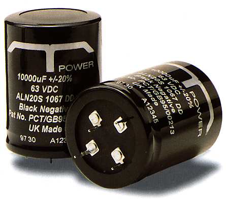
T-Network Capacitors On this Page : Usage Details Technical Data Availability DNM Design ™ keep large stocks of 10,000µF 63 volt T-Network Capacitors to provide quick access to this technology for researchers and DIY amp builders. This T-Network capacitor uses a combination of T-Network and Slit Foil technology to produce the ultimate audio capacitor. It is a typically ultra-reliable BHC electrolytic with performance exceeding even the most expensive specialist electrolytics. An audio-dedicated capacitor, the T-Network can be supplied for volume production at a realistic price giving a significant performance advantage that will be obvious in the product review. Production enquiries are particularly welcome. Repeatable production orders of 1000 pieces or more can be designed in capacitance sizes and voltages dedicated to the amplifier including custom sleeving and printing. Where required, technical assistance is available from DNM Design ™ and BHC Components. For all T-Network enquiries, to Denis Morecroft. |
|
T-Network Capacitors  The new T-Network capacitor (TNC) behaves
differently because the input must flow along
the capacitor plate to reach the output. The
signal is forced into pure capacitance with most
of the unwanted resistance and inductance
appearing on each side of the bulk
capacitance.
The new T-Network capacitor (TNC) behaves
differently because the input must flow along
the capacitor plate to reach the output. The
signal is forced into pure capacitance with most
of the unwanted resistance and inductance
appearing on each side of the bulk
capacitance.The residual component defects therefore tend to assist capacitive filtering in the T-Network design. Separation of Currents  In the TNC,
separation of the input and
output currents is maintained through the
connecting terminals and along the internal
tabs onto the capacitor plates. Due to the
unique current routing, the separation is still
effective during emission into the electrolyte.
In the TNC,
separation of the input and
output currents is maintained through the
connecting terminals and along the internal
tabs onto the capacitor plates. Due to the
unique current routing, the separation is still
effective during emission into the electrolyte.
The input currents are split equally in the foil plate and they travel only half the winding length. Displacement currents in the foil are therefore zero at the point where the output is taken from the plate. Even under high current conditions path resistance cannot cause voltage intermodulation between source and load. 
Tests have shown that the split input/output pathways of the new TNC allow peak current limiting to be used on bridge rectifiers without any loss of performance. The current limiting resistance damps rectifier diode resonances that cause high frequency radiation back into the mains supply. Improved Performance 
Most significantly, at this time, the TNC may help manufacturers meet the EMC standards. The TNC is designed for the most demanding filtering situations and it will redefine performance standards in many non-audio applications. In audio amplifiers TNC technology can be combined with Slit Foil technology to produce the ultimate audio capacitor. These capacitors give excellent results against standard components on a direct replacement. However, TNC high frequency performance is so enhanced that the H.F. compensation of test amplifiers may need resetting for best results. Capacitors in Audio Conventional reservoir capacitors combine input and output current paths generating spurious voltage from the charging current as it mixes with outgoing load current. This is a major limitation for an audio amplifier. The waveshape in the diode to capacitor line would be quite different from that in the capacitor to amplifier line except for the fact that the two share the same conductor inside the capacitor. This makes unwanted capacitor characteristics very critical. Test Results  A typical reservoir capacitor size of
10,000µF, 50V in TNC form was compared with
a two terminal, conventional capacitor, of
identical design using a Network Analyser,
calibrated for 4 port S parameter impedance
measurements.
A typical reservoir capacitor size of
10,000µF, 50V in TNC form was compared with
a two terminal, conventional capacitor, of
identical design using a Network Analyser,
calibrated for 4 port S parameter impedance
measurements.
Each capacitor was driven at a calibrated level from a 50 ohm source into a 50 ohm load and the load attenuation achieved was displayed against frequency between 10kHz and 100MHz. A simplified representation of the displayed result is shown. The standard capacitor showed increasing attenuation (input to output) from 10kHz up to 28kHz. Its attenuation then bottomed out and decreased, due to inductance, as the sweep frequency increased. The TNC was 4dB better in attenuation at 10kHz and it kept improving until 75kHz where it reached its maximum attenuation. At this point it is 11dB better than the standard capacitor. The standard capacitor showed increasing attenuation (input to output) from 10kHz up to 28kHz. Its attenuation then bottomed out and decreased, due to inductance, as the sweep frequency increased. The TNC did not deteriorate to the best attenuation of the standard capacitor until 1.4MHz. The TNC performance improvement is large enough to enable an improved product specification to be quoted in its various applications. The TNC will, in some cases, replace several large components with a single, more effective, one. Designing-in the T-Network The TNC installation requires the bridge rectifier diode feed to be separated from the output of the reservoir capacitors. Similarly the transformer centre tap (in a split-rail design) is separated from the reservoir centre tap. 
If the TNC is to be used as an upgrade option it is possible to design a PCB with a dual footprint to accept conventional and TNC components on the same PCB. BHC Components, in conjunction with DNM Design, will be pleased to help designers with any installation and design enquiries. 
Technical Data
Related documents : IEC 384-4 Temperature range Storage : -55°C to +85°C Operating : -40°C to +85°C Environmental classification : 40/085/56 Surge voltage 1000 surges (30 seconds) at 85°C with surge voltage applied. Charge/discharge 1,000,000 cycles at 25°C and rated voltage. One cycle per second with a time constant of 0.1. D.C. leakage current After application of rated d.c. voltage for 5 minutes at 20°C, the d.c. leakage current shall not exceed (0.006 C x U +4) µA. Where C is the rated capacitance in µF and U is the rated d.c. voltage. Vibration 10Hz to 500Hz at 0.75mm or 10g for 3x2hrs duration. Insulation resistance Voltage proof Ripple current The following values are approximate only, to give an indication of the effects of frequency and temperature on ripple current. More accurate data can be obtained by referring to the Application Notes available from BHC Components. Frequency Correction Capacitors shall withstand the rated r.m.s. ripple current as given in the tables at upper category temperature in circulating air. For frequencies other than those shown the following multipliers should be applied to the 100Hz ripple current.
Temperature Correction For ambient temperatures other than 85°C the following correction factors should be employed. Ambient Temperature Factor Temp. : Factor 30°C : 2.5 50°C : 2.1 70°C : 1.6 85°C : 1.0 N.B. The sum of the d.c. and a.c. voltage components should not exceed the d.c. voltage rating. Life expectancy 26,000 hours at rated temperature with rated voltage and ripple current applied. Capacitor marking The capacitors are marked with items 1 to 7 from the following list. 1. Rated capacitance in µF 2. Tolerance on rated capacitance 3. Rated voltage d.c. 4. BHC part number 5. Polarity of terminations 6. Patent number 7. Date code/Batch code Patent Number: PCT/GB95/00213 TNC and Slit Foil technologies combine to produce the ultimate audio capacitor. DNM Design ™ hold stocks of T-Network Capacitors for quick access to this technology. For OEM and retail enquiries, We have T-Network capacitors in 10,000 µF 63 Volt values. Capacitor Prices (N.B. : OEM enquiries are welcome and significant discounts are available for production volumes - 1 to 10 Capacitors £25 each, 11 to 20 Capacitors £21 each. Allow £5 post and packaging within the UK and £15 for Overseas. Post details of your order with a sterling cheque or bankers draft to DNM Design ™ at : 18, Hartford Road, Huntingdon, Cambridgeshire PE29 3QD, United Kingdom. Manufacturer : 
BHC Components Ltd 20-21, Cumberland Drive Granby Industrial Estate Weymouth Dorset DT4 9TE United Kingdom Tel. 01305 782871 BHC Components kindly gave permission to reproduce the information on this page. (This page is also available as a PDF file (437KB) written by BHC Components, which is particularly suitable for printing, or as a six-page brochure.) |
|||||||||||||||||||||||||||||||||||||||
<< Previous Products page Capacitors (overview) |
Next >> Technical Specifications |
|
|
© DNM Design ™ 2018 (Legal & Credits) |
| ||
|
>Products<
|
Contacts |
Principles |
||
 A normal power reservoir capacitor combines
the input and output in common current paths.
This produces resistance generated transient
voltages, during the charging cycle, as the
transient charging current mixes with the
outgoing load current.
In a normal capacitor unwanted resistance
and inductance force the input and output
together electrically, making its unwanted
characteristics very critical for good
performance.
A normal power reservoir capacitor combines
the input and output in common current paths.
This produces resistance generated transient
voltages, during the charging cycle, as the
transient charging current mixes with the
outgoing load current.
In a normal capacitor unwanted resistance
and inductance force the input and output
together electrically, making its unwanted
characteristics very critical for good
performance.